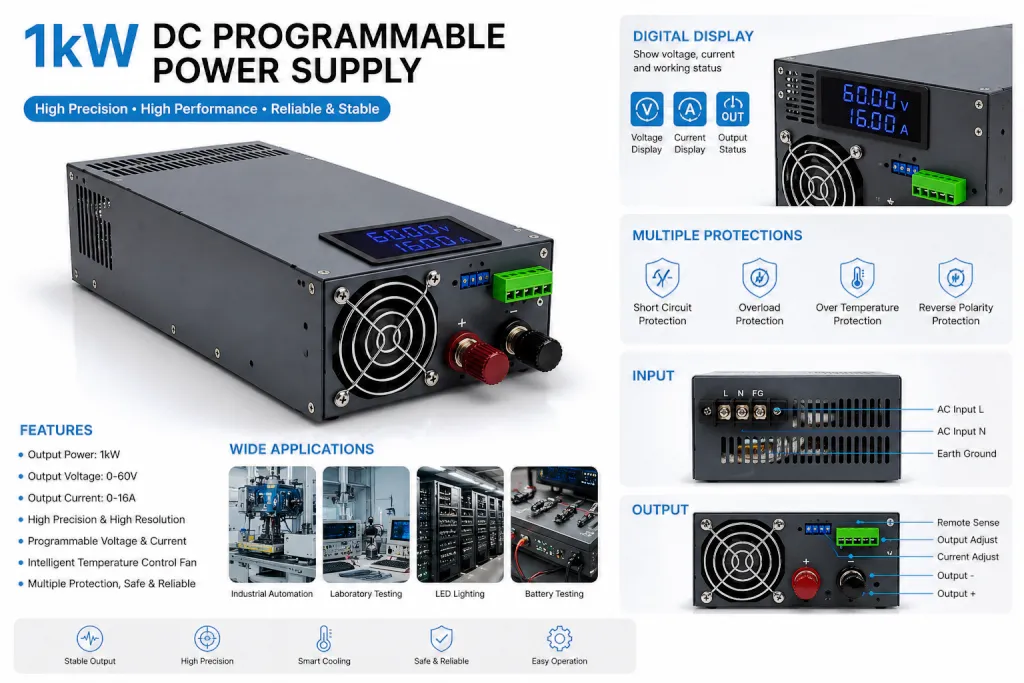
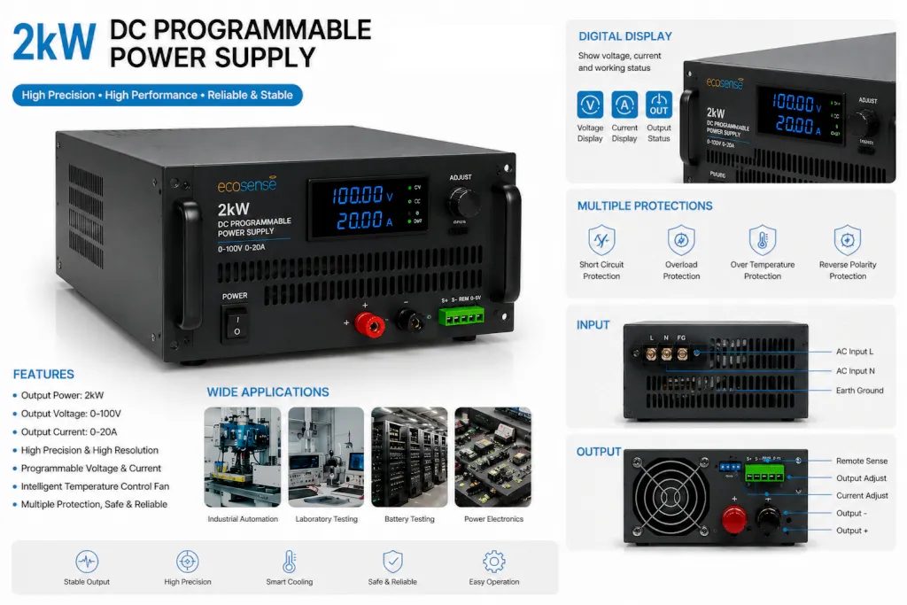
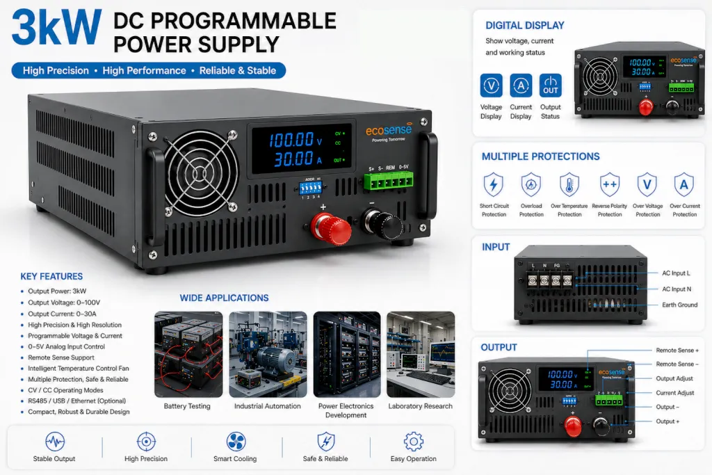
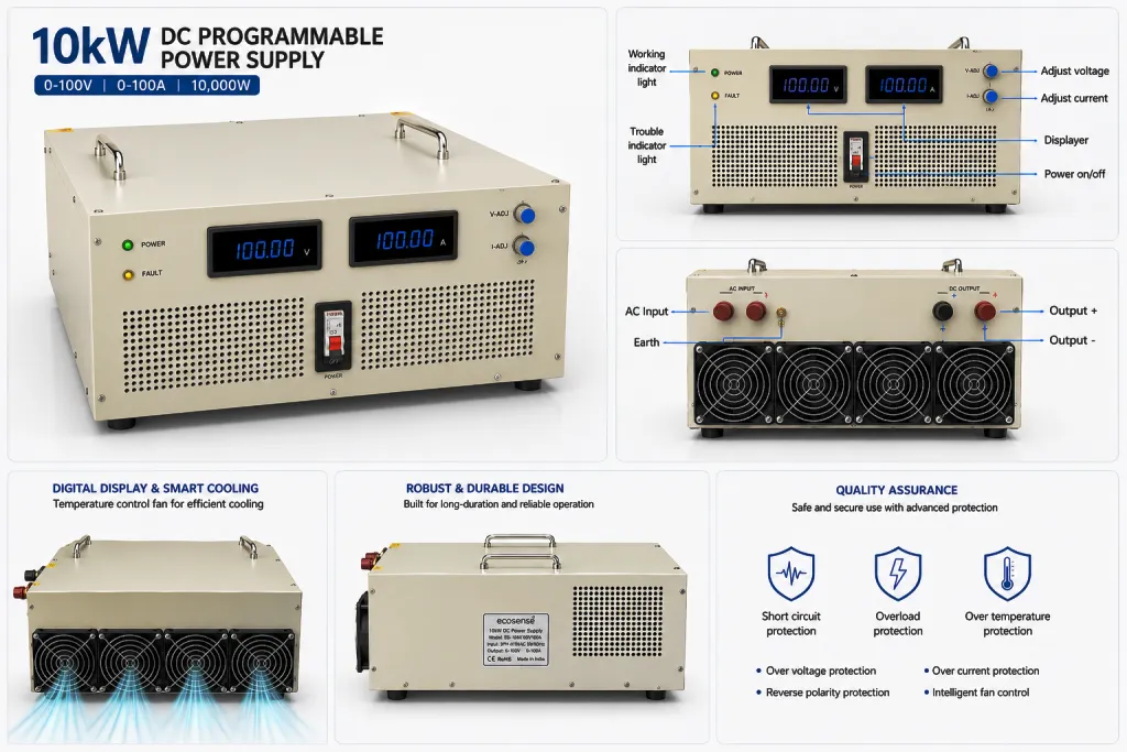
Programmable DC Power Supplies are intelligent and precision-controlled power systems designed to deliver stable DC voltage and current for testing, research, industrial automation, and product development applications. Unlike conventional power supplies with manual adjustments, these systems provide digital and external control capabilities, allowing users to accurately configure and monitor output parameters according to specific requirements.
The system supports 0–5V analog input control for both voltage and current adjustment, enabling integration with external controllers such as PLCs, microcontrollers, DAQ systems, and automation platforms. This makes the programmable DC power supply suitable for dynamic testing environments where output conditions need to change automatically based on system inputs.
These power supplies are widely used in electric vehicle systems, battery testing, renewable energy applications, laboratories, educational institutions, semiconductor testing, and industrial process control applications.
What is Programmable DC Power Supply?
A Programmable DC Power Supply is an electronically controlled power source capable of delivering adjustable and precisely regulated DC output. Users can define voltage and current parameters according to testing or operational requirements through digital interfaces or external control signals.
Unlike traditional power supplies that rely on manual operation, programmable systems allow automated control and repeatable testing procedures with higher accuracy and efficiency.
Key features include:
- Programmable voltage and current output
- 0–5V analog input for voltage adjustment
- 0–5V analog input for current adjustment
- High output accuracy and stability
- Multiple protection mechanisms
- Automation and integration capability
Programmable DC power supplies help create controlled testing environments while improving productivity and reducing manual intervention.
Why Choose a Programmable DC Power Supply?
- Precise Voltage and Current Control: The system provides accurate control over electrical parameters, ensuring reliable and repeatable operation for sensitive applications.
- External Analog Programming Capability: Support for 0–5V analog control inputs allows direct adjustment of voltage and current using external devices such as PLCs, controllers, or sensor-based systems.
- Automation-Friendly Operation: The programmable architecture enables seamless integration with automated test systems and industrial processes.
- Stable Output Performance: Intelligent regulation continuously maintains desired output values even during changing load conditions.
- Improved Testing Efficiency: Automated control reduces setup time and allows users to execute repeated testing procedures without manual adjustments.
- Enhanced Protection Features:Integrated safety mechanisms protect both the equipment and connected devices from abnormal operating conditions.
- Flexible Application Support: A single programmable system can support multiple research, testing, and industrial requirements.