
Electrolysis for Green Hydrogen Production
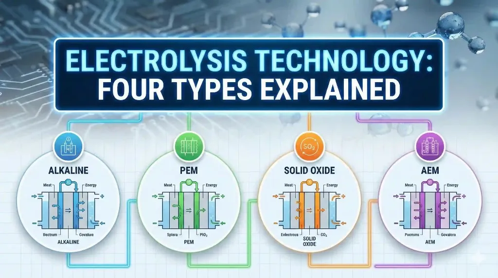
There are four main types of electrolysis used for hydrogen production: Alkaline (ALK), Proton Exchange Membrane (PEM), Anion Exchange Membrane (AEM), and Solid Oxide Electrolysis Cell (SOEC). Each type splits water (H₂O) into hydrogen and oxygen using electricity, but differs in operating temperature, electrolyte material, response speed, and cost. When powered by renewable electricity, these technologies produce green hydrogen — a zero-emission fuel central to India's National Green Hydrogen Mission and the global push toward net-zero industry.
What Is an Electrolyser?
Electrolysers are devices that use electricity to split water into hydrogen and oxygen. Water goes in. Hydrogen and oxygen come out. Everything else inside the system exists to control that process safely and repeatedly.
In green hydrogen setups, the electrolyser is connected to renewable power sources. That connection matters more than the design details. If the electricity is renewable, the hydrogen produced remains low-carbon. If it is not, the environmental benefit quickly disappears. This is why a water electrolyzer for hydrogen production is often treated as part of the energy system rather than a standalone machine.
Types of Electrolysis for Hydrogen Production
Different electrolyser designs exist because hydrogen is produced under very different conditions. Some plants run non-stop. Others only operate when renewable power is available.
A clear comparison of types of electrolyzer technologies helps institutions choose the right system based on their research goals, safety requirements, and budget
| Parameters | Alkaline | PEM | AEM | SOEC |
| What it is | The traditional electrolyzer that has been used for decades | A modern electrolyzer that uses a solid polymer membrane | A newer design that mixes ideas from alkaline and PEM systems | A high-temperature electrolyzer that works with steam |
| Electrolyte | Liquid alkaline solution (usually potassium hydroxide) | Solid polymer membrane | Solid membrane that works in alkaline conditions | Solid ceramic material |
| Operating temperature | Around 60–90 °C | Around 50–80 °C | Around 40–70 °C | High-temperature operation: about 650–850 °C |
| Ion that moves | Hydroxide ions (OH⁻) in liquid | Protons (H⁺) through the membrane | Hydroxide ions (OH⁻) through the membrane | Oxygen ions (O²⁻) through ceramic |
| How it works | Electricity splits water in an alkaline liquid; hydrogen forms on one side, oxygen on the other | Water splits at the anode; protons move through the membrane to form hydrogen | Similar to alkaline, but ions move through a solid membrane instead of liquid | Steam is split at high temperature; oxygen moves through the solid electrolyte |
| Catalysts used | Mostly nickel-based, low cost | Precious metals like platinum and iridium | Often non-precious metals | Ceramic and metal-ceramic materials |
| Response to power changes | Slow | Very fast | Fast | Slow (because it stays hot) |
| Energy Efficiency | 62-72% | 67-82% | 60-75% | 80-95% |
| Hydrogen Purity | 99.5-99.9% | 99.99%+ | 99.99%+ | 99.99% |
| Typical Scale | 1MW-100+MW | 1kW-10MW | 1kW-1MW(modular) | 100kW-1MW (pilot) |
Alkaline Electrolysis (ALK) - In Depth
Alkaline electrolysis is the most mature electrolysis technology — first commercialized in the 1920s and used continuously in fertilizer and chemical plants ever since. It uses a liquid potassium hydroxide (KOH) solution, typically at 25–30% concentration, as the conducting electrolyte between two nickel-plated electrodes separated by a porous diaphragm.
Hydroxide ions (OH⁻) carry charge through the liquid from the cathode to the anode, while electrons flow through the external circuit. Hydrogen forms at the cathode; oxygen forms at the anode.
CATHODE 2H₂O + 2e⁻ → H₂ + 2OH⁻
ANODE 4OH⁻ → O₂ + 2H₂O + 4e⁻
OVERALL 2H₂O → 2H₂ + O₂
✔ Strengths
- Lowest CapEx among the four types
- 50+ year operational track record
- No precious metal catalysts needed
- Scales to 100+ MW comfortably
✘ Limitations
- Slow ramp-up — poor fit for variable renewables
- Bulky footprint, low current density
- Lower hydrogen purity (needs post-purification)
- Liquid KOH requires careful handling
Proton Exchange Membrane (PEM) - In Depth
PEM electrolyzers replace the liquid alkaline electrolyte with a solid polymer membrane (typically Nafion) that conducts protons (H⁺) but blocks gases. Pure deionized water enters at the anode side; hydrogen exits the cathode side at high pressure (often 30+ bar without external compression).
The standout feature is dynamic response — PEM systems can ramp from 0% to 100% load in under a minute, making them the natural partner for solar and wind power profiles.
ANODE 2H₂O → O₂ + 4H⁺ + 4e⁻
CATHODE 4H⁺ + 4e⁻ → 2H₂
OVERALL 2H₂O → 2H₂ + O₂
✔ Strengths
- Sub-second response to power fluctuations
- Compact footprint, modular stacks
- Hydrogen purity 99.99%+ at output
- Output pressure 30+ bar (less compression)
✘ Limitations
- Requires platinum & iridium (expensive, scarce)
- Membrane degradation under impure water
- Higher CapEx than alkaline
- Maximum current density limits scale
Anion Exchange Membrane (AEM) - In Depth
AEM electrolyzers are the youngest of the four — commercializing since the late 2010s. They combine PEM’s solid-membrane simplicity with alkaline chemistry’s freedom from precious metals. The membrane conducts hydroxide ions (OH⁻) instead of protons, allowing the use of cheap nickel and iron catalysts while keeping a compact footprint.
For modular, distributed hydrogen — small refuelling stations, remote microgrids, on-site industrial supply — AEM is increasingly the answer.
CATHODE 2H₂O + 2e⁻ → H₂ + 2OH⁻
ANODE 4OH⁻ → O₂ + 2H₂O + 4e⁻
OVERALL 2H₂O → 2H₂ + O₂
✔ Strengths
- No precious metals — supply chain resilient
- Compact, modular, low maintenance
- Compatible with intermittent renewables
- Path to lowest LCOH at small scale
✘ Limitations
- Membrane longevity still being proven
- Limited commercial deployment data
- Smaller stack sizes (1 MW max today)
- Performance curves still improving
Solid Oxide Electrolysis Cell (SOEC) - In Depth
SOEC stands apart — it doesn’t electrolyse liquid water; it splits steam at 650–1000°C using a solid ceramic electrolyte (typically yttria-stabilized zirconia, YSZ). The high temperature lets it use heat to do part of the work, dramatically reducing the electricity needed per kilogram of hydrogen.
This is why SOEC pairs naturally with industrial sites that already produce waste heat — steel mills, ceramics kilns, ammonia plants. By recycling that heat, total efficiency climbs above 80–95%, the highest of any electrolysis technology.
CATHODE H₂O (steam) + 2e⁻ → H₂ + O²⁻
ANODE 2O²⁻ → O₂ + 4e⁻
OVERALL 2H₂O (steam) → 2H₂ + O₂
✔ Strengths
- Highest efficiency: 80–95% with waste heat
- Can operate in reverse mode (fuel cell)
- Co-electrolyses CO₂ + H₂O → syngas
- No precious metal catalysts
✘ Limitations
- Slow start-up & shut-down (thermal cycling)
- High-temperature materials are expensive
- Few commercial-scale plants today
- Not suited for variable renewable input
How It Works: A Look Inside the Electrolyzer
A water electrolyzer for hydrogen production operates through a sequence of controlled steps. First, the water is purified and deionized to remove impurities such as salts and chlorine. The purified water is then supplied to the electrolyzer using a controlled pumping system. Inside the electrolyzer, water molecules split into hydrogen and oxygen-related ions, depending on the electrolyte type.
Electrons flow through an external electrical circuit, while charged ions move internally through membranes or liquid electrolytes. Hydrogen forms on one side, oxygen on the other. The membrane electrode assembly ensures that hydrogen and oxygen remain physically separated. The produced gases contain moisture, which is removed using gas-drying systems before hydrogen and oxygen are collected separately.
If pressurized hydrogen is required, compression stages are added downstream of the electrolyzer.
Why Electrolysis-Based Green Hydrogen Matters
Not every energy problem can be solved with a cable and a battery. Heavy industry, chemical feedstocks, and long-duration storage all require something else.
Green hydrogen fits into existing industrial systems with fewer changes than many alternatives. It also offers a way to store renewable electricity when production exceeds demand. In grids with growing solar and wind capacity, this role becomes increasingly important.
Challenges & Considerations in Electrolysis for Green Hydrogen
Electrolysis is expensive when electricity is expensive. That reality dominates every business case.
Upfront costs are still high, especially for systems designed to handle fluctuating power. Some designs depend on specialized materials. Electrolysers use clean water which is again a challenge in water-scarce regions. Even if clean water is available purification adds cost and losses. Beyond production, hydrogen must still be compressed, stored, and moved, which adds cost and complexity.
Conclusion
In short, the shift toward green hydrogen isn't just about the chemistry of water—it’s about finding the best way to "bottle" renewable energy.
The industry has moved past the stage of searching for a single "winner." Instead, we are seeing a toolkit approach:
- Alkaline remains the workhorse for massive, steady industrial plants.
- PEM serves as the flexible bridge for erratic wind and solar power.
- AEM and SOEC represent the next frontier, aiming to slash costs and maximize efficiency through heat integration.
Ultimately, the "best" electrolyser is the one that fits the local environment. Whether an operator prioritizes low upfront costs, rapid response to a shifting power grid, or the use of industrial waste heat, the technology is now mature enough to move out of the lab and into the global energy infrastructure. As renewable electricity becomes the standard rather than the exception, these four technologies will be the primary engines driving a carbon-neutral industrial future.