
Connecting Solar Panels in Series Vs Parallel
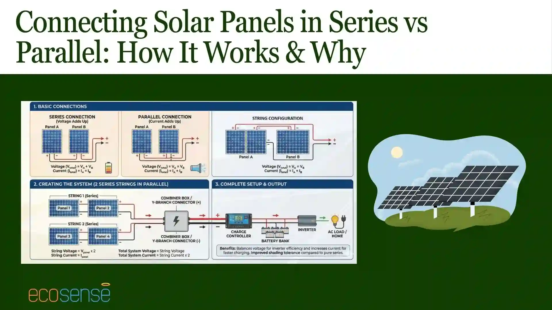
Series wiring connects solar panels positive-to-negative in a single line — voltages add up while current stays the same. Example: four 18V/6A panels in series produce 72V at 6A. Best for: long wire runs, MPPT charge controllers, full-sun conditions, low-amperage systems.
Parallel wiring connects all positives together and all negatives together — currents add up while voltage stays the same. Example: four 18V/6A panels in parallel produce 18V at 24A. Best for: partial shading, PWM charge controllers, low-voltage 12V battery systems, shorter wire runs. The choice depends on your charge controller type, shading conditions, wire run length, and downstream equipment voltage requirements.
Introduction
Most people working with solar panels already understand series and parallel connections. That part is not the challenge. The real decision begins when the panels need to be connected to something—an inverter, a charge controller, or a battery bank. At that stage, wiring is no longer about theory. It becomes about matching voltage and current ratings correctly. The choice between series and parallel depends on what the downstream equipment can accept, how much voltage it requires to operate efficiently, and how much current it can safely handle. Get that match right, and the system runs smoothly. Get it wrong, and performance, safety, and reliability all suffer.
Voltage, Current & Power: The Three Variables That Matter
Voltage (V)
The electrical "pressure" pushing current through the circuit. Higher voltage = less loss over long wire runs. Solar panels have a rated voltage (Vmp ~18V, Voc ~22V for typical 12V-class panels).
Current (A)
The flow rate of electricity, measured in Amperes. Higher current = thicker cables needed (more copper, more cost). Panel current ratings are Imp (max power) and Isc (short circuit).
Power (W)
The actual energy output. P = V × I. A 400W panel could be 40V × 10A or 20V × 20A — same power, different distribution. Series and parallel change the V/I split, not the total power.
What Does “Series Connection” Mean in a Solar PV System?
A series connection links panels one after another. Series connection means connecting positive terminal of one panel to the negative terminal of the next. When panels are connected in this manner, the voltages add up while current remains the same. For example, when 4 panels of 10V and 2A are connected in series the resultant voltage becomes 40V while resultant current is still 2 A. The resultant current and voltages are measured between positive terminal of first panel and negative terminal of the last one. This method of connecting solar in series is used when the system needs higher DC voltage and low current to operate efficiently.
Understanding Series vs Parallel Connections in Solar Systems
Series and parallel wiring solve different problems. Series wiring raises voltage. Parallel wiring raises current. That single difference drives most design decisions. High-voltage systems benefit from series strings because lower current means lower cable losses. That explains why solar panels are connected in series in grid-tied systems. Parallel wiring keeps voltage fixed and add current instead. It is common in battery-based setups where voltage limits are strict. Neither approach is “better” on its own. Each matches a specific operating need.
In a standalone solar PV system, the choice between series and parallel wiring directly determines whether the system meets the charge controller's input voltage window and the battery bank's charge current requirements
Series vs Parallel Solar Panels: Side-by-Side Comparison
How Series Connection Changes the Electrical Output of Solar Panels
When panels are connected in series, their voltages add up. Four identical panels produce four times the voltage of one panel, but the same current. Higher voltage reduces resistive losses in cables and improves inverter efficiency. This efficiency gain is a key reason why solar cells are connected in series. The downside is sensitivity. If one panel underperforms, the entire string is affected. Bypass diodes help, but the weakest panel still sets the limit. Series wiring rewards uniform conditions and careful layout.
Impact of Shading on Series vs Parallel Configurations
This is Battle Born Batteries' strongest competitive angle — they have an entire section dedicated to shading impact with specific numbers ("output might drop to 150W or less" from 300W with one panel 50% shaded in series). Your page does not mention shading. This is a major gap because shading is the #1 reason real-world solar arrays underperform.
Shading on a Series String
If one panel in a series string is shaded, the entire string's current drops to match the weakest panel — because current is the same throughout a series circuit. Example: Three 100W panels (300W total) wired in series. One panel gets 50% shaded → string output drops to ~150W or less. The shaded panel becomes a bottleneck for the whole string. Bypass diodes (built into modern panels) mitigate but do not eliminate this effect.
Shading on a Parallel Array
If one panel in a parallel array is shaded, only that panel's output drops — the others continue producing at full capacity, because each panel has its own current path. Same example: Three 100W panels in parallel. One gets 50% shaded → output is ~250W (200W from two full panels + 50W from the shaded one). Parallel wiring is significantly more shading-tolerant.
When to Use Series, Parallel or Series-Parallel Wiring
Series wiring works well when panels receive similar sunlight and the inverter requires higher voltage. Parallel wiring suits systems where shading varies or where batteries fix the system voltage. Many real installations fall somewhere in between. That’s where series-parallel wiring comes in. Panels are grouped into series strings, then those strings are connected in parallel. This balances voltage, current, and reliability. It also makes future expansion easier, which is why larger systems rarely rely on a single wiring method.
How to Set Up Your System in Parallel?
In a parallel configuration, all positive terminals connect together, and all negative terminals connect together. The system voltage stays the same as one panel. Current increases as more panels are added. This approach is common in off-grid and battery-based systems. Parallel wiring handles partial shading better because one weak panel does not pull down the rest. The trade-off is higher current, which demands thicker cables and proper protection.

Fig.1 Parallel connection of Solar Panels
How to Set Up Your System in Series?
In a series setup, panels are connected in a chain until the required voltage is reached. This layout is typical in grid-connected systems and clearly shows why solar panels are connected in series. Lower current simplifies cabling and improves efficiency over longer distances. Designers must account for temperature effects, since panel voltage rises in cold conditions. Ignoring this can push string voltage beyond inverter limits.

Fig.2 Series connection of Solar Panels
How to Set Up Your System in Series-Parallel?
Series-parallel wiring starts with series strings. Those strings are then connected in parallel. This allows voltage and current to be tuned independently. It is widely used in commercial rooftops and institutional projects. Series-parallel layouts improve fault tolerance, reduce mismatch losses, and simplify maintenance. The system continues operating even if one string underperforms.

Fig.3 Series & Parallel combination connection of Solar Panels
Conclusion
Solar wiring is not an afterthought. It shapes how the entire system behaves. Connecting solar cells in series improves efficiency and suits high-voltage designs. Parallel wiring offers flexibility where voltage must stay low. Series-parallel layouts balance both. The right choice depends on site conditions, equipment limits, and future plans. Good wiring design is invisible when done right—and expensive when done wrong.