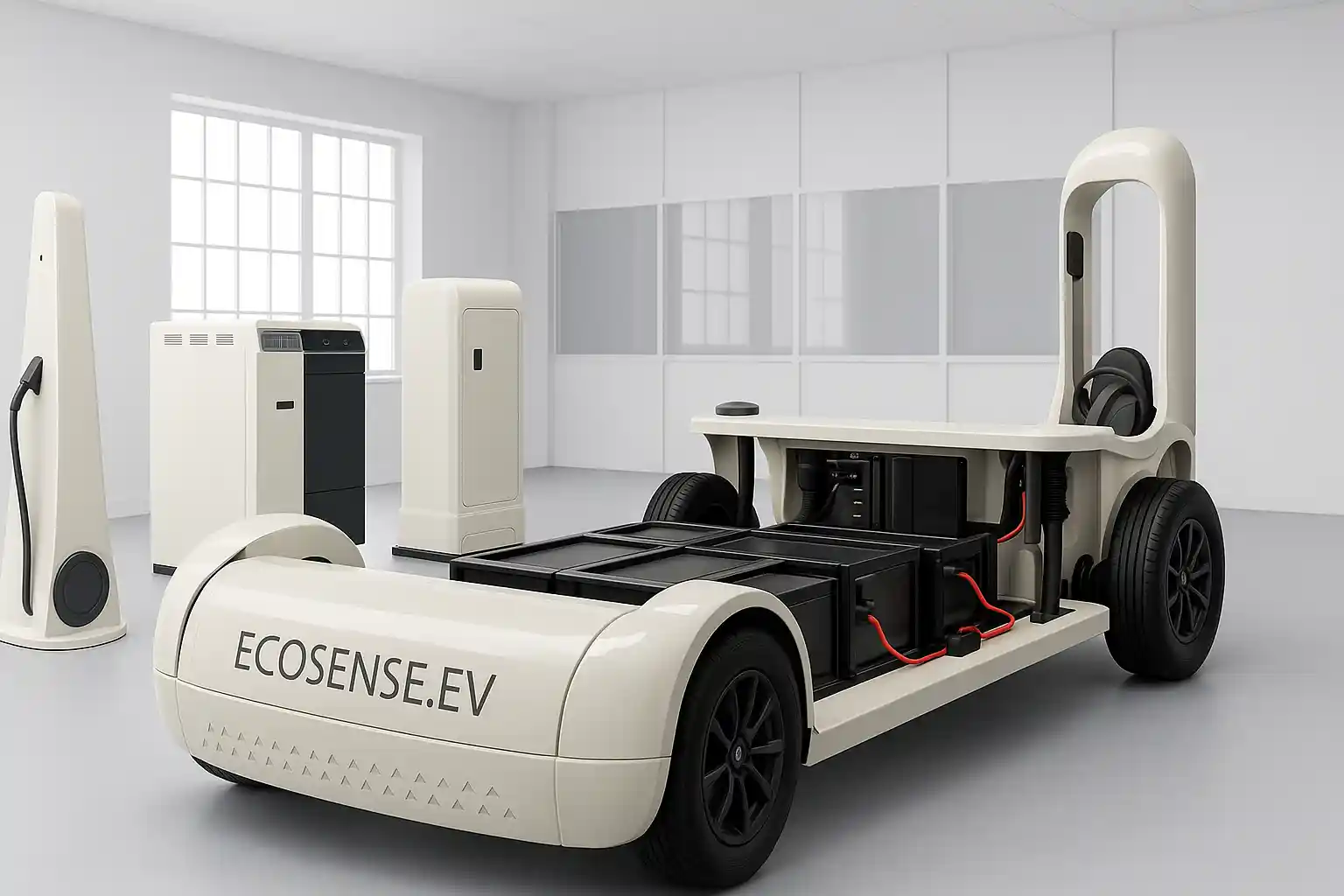
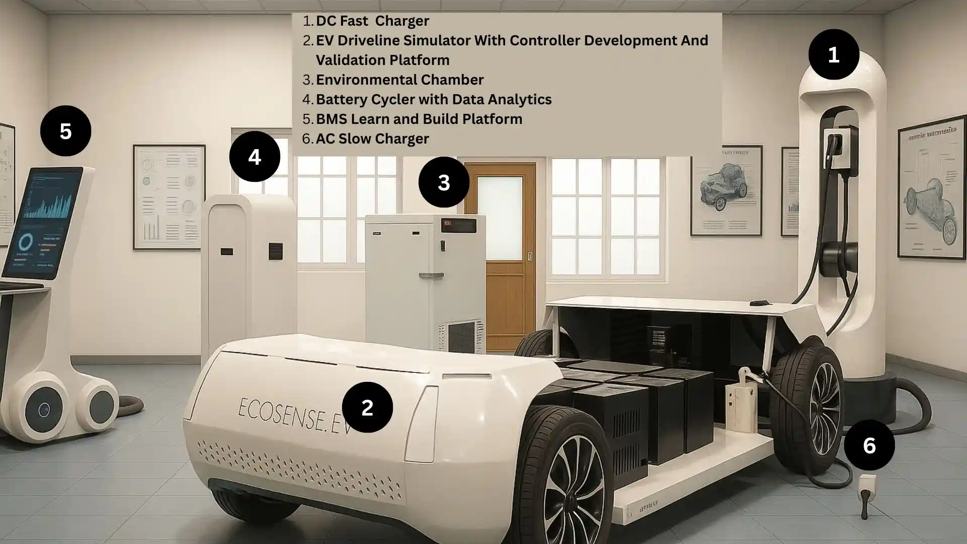
EV Drive Line Simulator with Controller Development & Validation Platform 

The EV Driveline Simulator with Controller Development & Validation Platform is a complete hardware-integrated environment designed for mastering electric vehicle propulsion systems. It enables students, researchers, and engineers to design, test, and validate motor control algorithms on real PMSM traction motors, interact with a programmable dynamometer, execute drive cycles, and evaluate full charging–discharging workflows. The platform replicates a true EV energy ecosystem—from grid to battery to motor and back—making it ideal for advanced learning, research, and prototype development in electric mobility. 

Key Features

  • Real EV-Grade PMSM Driveline: Includes PMSM traction motor enabling hands-on study of real EV motor behaviour under varied load and speed conditions.
  • Programmable Motor Controller: Supports FOC, V/f, BLDC commutation, and custom algorithm deployment, allowing complete control strategy experimentation.
  • PMSM-Based Dynamometer: Provides static and dynamic loading using rectifier-based resistive load banks to simulate real road load scenarios.
  • Complete Energy Flow Simulation: Covers grid → OBC → battery → motor → dynamometer → resistive load/grid, enabling true EV system replication.
  • Regenerative Braking Evaluation: Captures and processes regenerated energy through the rectifier-resistive load system or feeds it back to the battery depending on mode.
  • Integrated Lithium-Ion Traction Battery Pack: Features LiFePO₄ pack with smart BMS for SOC, SOH, cell balancing, and protection analytics.
  • Programmable Onboard Charger (OBC): Allows CC, CV, and CC-CV charging with adjustable parameters and EVSE pilot-signal communication.
  • Integrated Auxiliary battery: to power accssories like headlight, taillight horn etc just like a real EV.
  • Real AC EVSE Charging Interface: Supports Level-2 charging with safety checks
  • High-Speed Data Acquisition System: Provides >10 kHz sampling for voltage, current, torque, speed, and temperature with real-time visualization.
  • Central FPGA-Based Control: NI FPGA card enables deterministic control, fast data handling, and experiment automation.
  • Drive Cycle Implementation: Allows execution of IDC and custom drive cycles for efficiency, energy consumption, and regeneration studies.
  • Modular & Open Architecture: All subsystems are plug-and-play with open access to control parameters, ideal for education, research, and prototyping.
Ecosense

Learning Modules 

Ecosense

EV Driveline & Motor Control

  • PMSM traction motor operation and torque-speed characteristics
  • Field-Oriented Control implementation and tuning
  • Four-quadrant operation and dynamic response analysis
  • Custom motor control algorithm deployment
  • Efficiency mapping across load and speed ranges

Drive Cycle Implementation & Regeneration

  • Indian Drive Cycle (IDC) execution and analysis
  • User-defined torque/speed drive profile creation
  • Regenerative braking and energy recovery evaluation
  • SOC-dependent motor behaviour study
  • Performance comparison across multiple drive cycles
     

Battery & Charging System Analysis

  • Li-ion traction battery charging/discharging behaviour
  • OBC operation under CC, CV, and CC-CV modes
  • EVSE handshake, pilot-signal, and safety protocol study
  • Regenerative charging impact on battery thermal performance
  • Parameter logging and correlation with system efficiency

Working Principle

  • The traction motor is powered through a traction battery via a programmable inverter that executes FOC, V/f, or custom control algorithms.
  • The traction motor drives a PMSM-based dynamometer, which applies variable mechanical load using a rectifier-resistive load bank or via a programmable inverter connected to grid.
  • Regenerative braking is simulated by routing generated energy back to the traction battery.
  • The on board charger charges the traction battery from an AC EVSE using CC, CV, or CC-CV profiles with full pilot-signal communication.
  • The traction battery charges auxiliary battery which powers accessories like headlight, taillight, horn etc.
  • The BMS monitors cell voltages, temperature, SOC, and SOH to ensure safe charging and discharging.
  • An FPGA-based controller synchronizes inverter commands, drives the dynamometer load, and manages drive cycle execution.
  • A high-speed DAQ system logs voltage, current, torque, speed, and temperature in real time for analysis and validation.
Ecosense

Technical Specifications 

Ecosense

Driveline and Powertrain Components

Components Specifications
Traction Motor PMSM, 5 kW, 72 V AC, 3000 RPM, >90% efficiency
Dynamometer PMSM, 5 kW rated / 10 kW peak, 80–120 Nm torque range, 0–5000 RPM, rectifier + 5 kW resistive load
or
PMSM, 5 kW rated / 10 kW peak, 80–120 Nm torque range, 0–5000 RPM with Programmable 3 Phase inverter feeding to grid
Motor Controller Programmable Three Phase Inverter, 150 V DC link, 25 A output, 10 kHz switching, FOC/V/f/BLDC modes, forced-air cooling

*These specifications can be customized as per requirement

Battery, Charging & Energy System

Component Specifications
Traction Battery with BMS LiFePO₄, 72 V, 200 Ah, >3000 cycles, 0.5C/1C charge &discharge with smart BMS
Auxiliary Battery 12 V, Lead-acid sealed battery
On-board Charger 300–350 V input, 80 V output, 1.5 kW, IGBT-based buck converter, 10 kHz switching
Auxiliary Battery Charger 70–80 V input, 14 V output, 500W, IGBT-based buck converter, 10 kHz switching
AC Charger (EVSE) unit Level-2 charger, 60–90 V battery compatibility, 3.3 kW rating, pilot signal communication

*These specifications can be customized as per requirement

Control, DAQ & Communication

Component Specifications
Central Controller NI sbRIO-9607, NI-9684 mezzanine card, 667 MHz ARM, Xilinx Zynq-7020 FPGA
DAQ System 16-bit resolution, 180 kS/s/ch, ±0.64% accuracy
I/O Interfaces CANbus, RS-232, RS-485, Gigabit Ethernet, USB 2.0
Digital &Analog I/O 14 high-speed half-bridge outputs, 24 sinking outputs, 28 sourcing inputs, 32 FPGA LVTTL lines

*These specifications can be customized as per requirement

Related Products

Frequently Asked Questions

An EV Drive Line Simulator allows students and researchers to study real EV propulsion behaviour without a full vehicle. It replicates the interaction between motor, inverter, controller, and mechanical load, enabling safe analysis of torque, speed, efficiency, regenerative braking, and drive-cycle response under controlled laboratory conditions.

Yes. The system is specifically designed for controller development and validation. Users can implement custom motor control algorithms, tune parameters, and validate performance under varying load and speed conditions. This supports experimentation with real hardware before vehicle-level deployment, reducing risk and development time.

The platform supports experimentation with commonly used EV traction motors such as PMSM, BLDC, and induction motors. Its modular architecture allows the motor, inverter, and controller to be reconfigured, enabling comparative studies of different motor technologies and their control strategies.

The dynamometer emulates real vehicle load conditions by applying controlled mechanical resistance to the traction motor. This allows users to study acceleration, steady-state operation, regenerative braking, and efficiency under simulated driving scenarios without requiring an actual vehicle or road testing.

Yes. For teaching, it provides hands-on exposure to EV driveline fundamentals and control concepts. For research, it supports advanced controller validation, drive-cycle analysis, efficiency mapping, and fault studies, making it suitable for undergraduate labs, postgraduate research, and industry-oriented EV development projects.

Get in Touch

Ready to transform your labs?

Contact Now