Fuel Cell Drive Train 

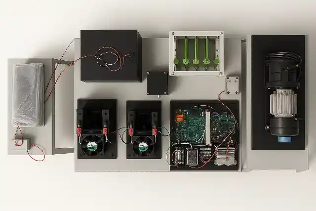
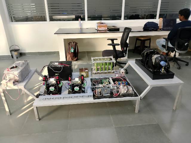
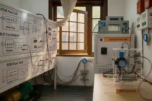
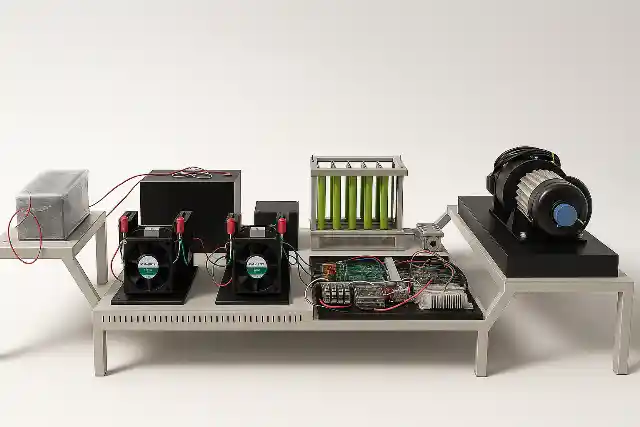
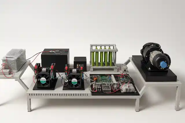
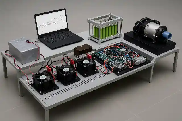
The Fuel Cell Drive Train is a modular laboratory platform designed to simulate and study the complete electric drive train of a hydrogen fuel cell hybrid electric vehicle (FCEV). It provides a hands-on learning environment that demonstrates how hydrogen energy is converted into electric propulsion through coordinated interaction between power electronics, energy storage systems, and motor drives. This lab-scale system integrates a PEM fuel cell, bidirectional power converters, battery bank, ultracapacitor module, and a complete motor drive setup. The traction system consists of a Permanent Magnet Synchronous Motor (PMSM) mechanically coupled to a PMDC loading motor and resistive load bank, enabling controlled road condition and load profile simulation. The architecture closely mirrors a real vehicle electric drive train, allowing detailed study of component-level and system-level behavior. 

Key Features

  • Modifiable Control Algorithms: Includes open-source application software with an FPGA-based controller, enabling users to customize inverter control strategies and implement programmable drive cycles.
  • Hybrid Fuel Cell–Battery–Supercapacitor Architecture: Combines a PEM fuel cell, 72 V battery bank, and 48 V supercapacitor to demonstrate practical hybrid energy management used in advanced electric drive train systems.
  • Fuel Cell Charging via Controlled Boost Converter: The fuel cell output is interfaced through a boost DC–DC converter with MATLAB-based current reference control, allowing precise regulation of fuel cell operating points.
  • Smart Battery Bank with Advanced BMS: The 72 V, 24 Ah battery pack is equipped with a smart BMS featuring voltage, current, and temperature protection, coulomb counting, and RS-485 communication.
  • Bidirectional Supercapacitor Energy Interface: A bidirectional DC–DC converter enables controlled supercapacitor charging and discharging, supporting peak power demand and reducing battery stress during transients.
  • High-Performance PMSM Traction Drive: Inverter-fed PMSM traction motor allows accurate speed and torque control, closely representing propulsion dynamics in an automotive electric drive train.
  • Realistic Load Emulation: A mechanically coupled PMSM loading motor operates as a generator, converting mechanical energy back into electrical energy that is dissipated through a resistive load.
  • MATLAB-Based Closed-Loop Control Platform: The complete system operates under MATLAB/Simulink using a TI C2000 controller, supporting real-time monitoring, tuning, and control experimentation.
  • Comprehensive Instrumentation: Integrated voltage, current, speed, and torque sensors enable detailed efficiency and loss analysis across the entire electric drive train.
  • Safe and Modular Laboratory Design: DC MCBs, high-current relays, electrical isolation, and sensor-based protection ensure safe operation with flexible experimental reconfiguration.
Ecosense

Learning Module 

Ecosense

Fuel Cell Power Generation & Conditioning

  • Study PEM fuel cell voltage–current characteristics under controlled charging conditions.
  • Analyze boost converter operation for fuel cell voltage regulation.
  • Implement current-controlled battery charging using MATLAB.
  • Observe fuel cell behavior under different load demands.
  • Evaluate fuel cell efficiency and power stability.

Hybrid Energy Storage & Power Management

  • Understand energy sharing between battery and supercapacitor.
  • Perform bidirectional power flow experiments using the DC–DC converter.
  • Analyze supercapacitor role during transient and peak load conditions.
  • Study battery stress reduction using supercapacitor buffering.
  • Develop basic energy management strategies for hybrid drivetrains.

Electric Drive & Load Simulation

  • Operate PMSM traction motor under no-load and loaded conditions.
  • Analyze motor speed and torque control via inverter drive.
  • Study regenerative behavior using PMSM loading motor and rectifier.
  • Measure electrical and mechanical efficiency of the drivetrain.
  • Simulate real EV driving loads in a controlled laboratory setup.

How the Fuel Cell Drive Train System Works

    • Hydrogen is supplied to the PEM fuel cell, where an electrochemical reaction generates DC electrical power.
    • The fuel cell produces a variable DC output voltage based on load and operating conditions.
    • A boost DC–DC converter regulates the fuel cell output, operating under a MATLAB-defined current reference.
    • Regulated power is used to charge a 72 V battery bank, which acts as the primary energy source for the system.
    • A 48 V supercapacitor is interfaced with the battery through a bidirectional DC–DC converter.
    • The supercapacitor supports rapid charge and discharge during transient and peak load conditions.
    • During high power demand, the supercapacitor assists the battery to reduce current stress and improve response time.
    • The battery supplies DC power to the PMSM motor controller.
    • The motor controller drives the PMSM traction motor with controlled speed and torque.
    • The traction motor is mechanically coupled to a loading motor to simulate real vehicle load conditions.
    • The loading motor operates as a generator, converting mechanical energy back into electrical energy.
    • Generated electrical energy is rectified and dissipated through a resistive load bank.
    • Real-time sensing of voltage, current, speed, and torque enables continuous monitoring of power flow and efficiency across the electric drive train.
  • Ecosense

    Technical Specifications 

    Ecosense

    Energy Sources & Storage


    ParametersSpecifications
    Fuel Cell InterfaceBoost-converter-based charging
    Battery Bank72 V, 24 Ah with smart BMS
    Battery Charge / Discharge Rate1C / 1C
    Supercapacitor48 V, 165 F
    Supercapacitor Charge / Discharge10 A / 10 A

    * specifications can be customized as per user's requirement

    Power Electronics & Control


    ParametersSpecifications
    Boost Converter28–44 V input, 72 V output
    Boost Rated Power1 kW
    Bidirectional ConverterFor Battery & Supercapacitor
    Converter Switching Frequency10 kHz
    Controller PlatformMATLAB with TI C2000

    * specifications can be customized as per user's requirement

    Drive & Load System


    ParametersSpecifications
    Traction MotorPMSM, 1 kW
    Rated Voltage72 V
    Rated Speed1500 RPM
    Load EmulationPMSM generator + resistive load
    Load Rating1 kW resistive bank

    * specifications can be customized as per user's requirement

    Related Products

    Frequently Asked Questions

    Electric vehicle drivetrains are broadly classified into Battery Electric Vehicle (BEV) drivetrains, Hybrid Electric Vehicle (HEV) drivetrains, Plug-in Hybrid Electric Vehicle (PHEV) drivetrains, and Fuel Cell Electric Vehicle (FCEV) drivetrains. Fuel cell drivetrains use hydrogen as the primary energy source, combined with electrical energy storage for dynamic operation.

    The fuel cell generates DC power, which is conditioned through a DC–DC converter to charge the battery bank. The battery supplies regulated DC power to the motor controller, which converts it into controlled three-phase AC to drive the PMSM motor with precise speed and torque control.

    Fuel cell drivetrains offer zero tailpipe emissions, high energy efficiency, fast refueling compared to batteries, and extended operating range. Hybrid integration with battery and supercapacitor improves transient response, reduces battery stress, and enhances overall system efficiency.

    Key limitations include high system cost, hydrogen storage and infrastructure challenges, complex energy management requirements, and lower overall efficiency when hydrogen production and storage losses are considered.

    Get in Touch

    Ready to transform your labs?

    Contact Now