Ecosense Sustainable Solutions Pvt. Ltd. establishes a 1kW Fuel Cell lab at the Indian Institute of Technology, Jammu following all the Standard operating procedures defined by the government authorities of Jammu and Kashmir and Indian Institute of Technology, Jammu.
Ecosense is working tirelessly to enable institutions pan India with renewable energy technology. Our Engineers and Technicians are following all the standard operating procedures and working in Institutes wearing Personal Protective Equipments (PPE) kit, to fight the COVID-19 pandemic and work efficiently.
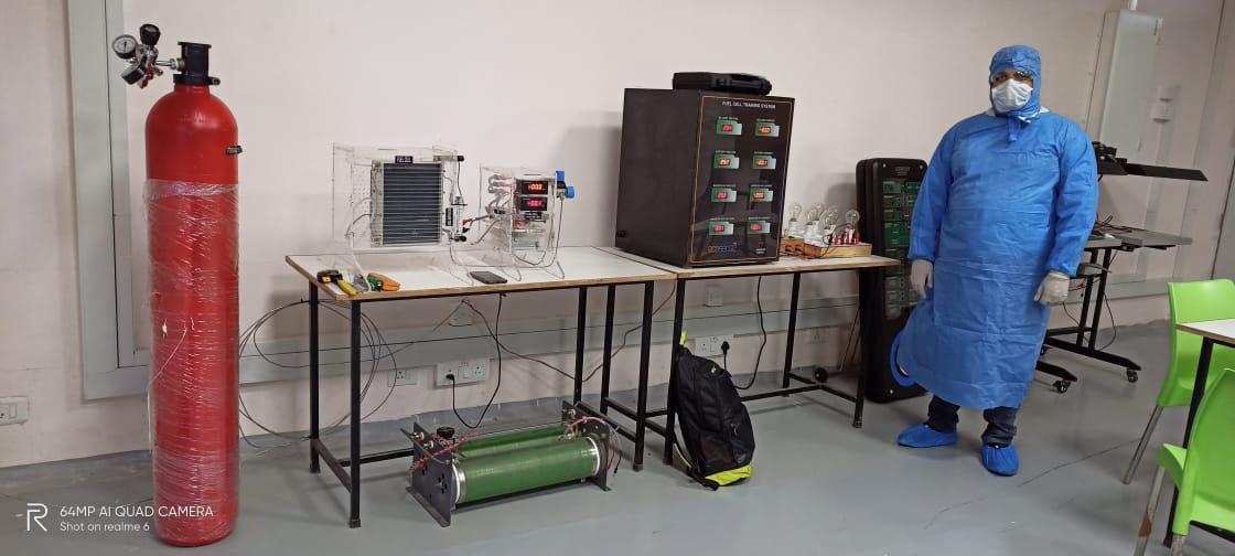
Ecosense personnel demonstrating the Fuel Cell Training System at IIT, Jammu
What is Fuel Cell?
A fuel cell is an electrochemical device that, like any battery, converts chemical energy into electrical energy. The concept of the fuel cell is not new; the first working cell was developed in the late 1830’s by William Robert Grove (1811-1896), who referred to his device as a “gas battery”. “Battery” is a good descriptive term for a fuel cell, which in the strictest sense can be looked upon as a primary battery whose chemical fuel is constantly replenished.
How Fuel Cell Works?
The operating principle of the proton-exchange-membrane-hydrogen-based fuel cell is relatively simple. The overall fuel cell as a unit is composed of a number of stacked cells (similar to the cells of a car battery). Each cell in the stack is composed of a cathode and anode which are separated by the proton exchange membrane. The PEM serves as an insulator between the adjacent “half cells” while providing a pathway for migration of hydrogen protons created during the process. Hydrogen is feed to the anode side of each cell and air or oxygen to the cathode side. Electrons are given up by hydrogen on the anode side, directed through an external circuit and then return to the system on the cathode side where they recombine with hydrogen ions and oxygen to form water. The process is described in a bit more detail below.
The process of power generation begins with hydrogen at the anode side of the cell. The proton exchange membrane is coated with a special platinum catalyst that causes hydrogen molecules coming in contact with it to split into two H+ ions (hydrogen ions). The formation of the positive hydrogen ion requires that each hydrogen atom, from the original hydrogen molecule, give up an electron. This is where the graphite comes in, as these now “free” electrons are conducted away by the highly conductive graphite anode and are directed through an external circuit where they provide energy. At the anode the hydrogen is oxidized (its electrical charge in increased due to the shedding of electrons which results in an increased positive charge). The newly formed hydrogen ions (protons) continue to move through the proton exchange membrane while on the cathode side of the cell oxygen molecules moving into the surface of the proton exchange membrane are cleaved into two highly reactive oxygen atoms(the oxygen molecule, O2, is relatively stable while oxygen atoms are not). While all of this is occurring the electrons released from the hydrogen molecules, previously at the anode, return from the external circuit through the highly conductive graphite cathode. At the interface of the proton exchange membrane and cathode one oxygen atom, two hydrogen ions, and two returning electrons combine to form a water molecule. At the cathode, the overall reaction is a reduction (electrons are added to oxygen reducing its charge).
Overall, in the cell stack, hydrogen is oxidized, oxygen is reduced, electrons are liberated and reunited, and the “chemical pressure” of all of this is used to provide power. The by-product of this electrolytic “combustion” is water, which is vented to the atmosphere. The above process occurs in each cell of the stack as long as fuel is provided. Each cell is pumping electrons released from the previous cell resulting in an overall stack pressure, or voltage, which is equal to the voltage of each cell multiplied by the number of cells that are in series (the total number of cells in the stack).
Ecosense’s Fuel Cell Training System:
Ecosense’s Fuel Cell Training system is a standalone Fuel Cell system, with the output of fuel cell is connected to a charge controller and charge controller is further connected to a battery, an inverter, and AC and DC Loads to run utilities.
Fuel Cell unit receives dry hydrogen from the Hydrogen gas cylinder at preset LPM. The generated power can be used directly by a DC load but as per the V-I curve of Fuel cell system, the voltage reduces as we increase the load, therefore, the power generated by fuel cell system cannot be used directly hence the output is connected to a charge controller which charges the battery and maintain output as per the battery voltage. The battery bank is further connected to a home inverter so that home utilities can be used as a load for the fuel cell system.
Learning Outcomes of Ecosense’s Fuel Cell Training System:
• Draw Characteristics of fuel cell with the help of resistive load or DC-DC converter
• Output power variation of fuel cell with change in Hydrogen supply
• Evaluate Fuel cell system performance with only DC load connected to the charge controller with battery bank
• Evaluate Fuel cell System performance with only AC load connected to the inverter with battery bank.
• Evaluate Output power variation of the fuel cell with a change in temperature.

Block Diagram of Fuel Cell Training System
Advantages of Fuel Cell Training System:
Apart from the standard learning outcomes, a user can also explore the following research options with the system• System can be developed as a grid-connected system.
• System can be developed as a hybrid grid-connected system.
• Using Power Electronics converters instead of the charge controller and inverter, the user can test MPPT algorithms and different control algorithms.